
| Previous Page | Glass Blowing Menu | Main Menu |
|---|
Making a closed-off triode that works properly is a demanding project. It has taken a long time to develop the equipment and techniques required, to the point where I could attempt making one. This page documents my first attempt, which was partially successful. Many of the ideas used were inspired by Claude Paillard.
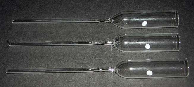
The envelope was made from a length of 22mm OD AR-Glas (soda-lime glass) tube from Schott UK. The first exhaust tube used 5mm OD soda-lime glass tube from Fisher Scientific. To make the assembly, first a 160mm length of the 22mm tube is suspended from a slowly rotating rubber bung and torched in the middle. The bottom half of the tube drops under gravity when the glass softens. The motor must be stopped just before the bottom half hits the bench. Each half ends up with a cone shaped end and and can be used to make an envelope. The end of the cone is cut off and made square using a fine flat metalwork file. The tube is then mounted in the lathe using a bung on a rod and run at low speed. The cone end is gently heated with a yellow flame and then torched with the plumbers blow-torch so that the end rounds and the hole closes to about 3mm.
A 2mm diameter metal rod is then pushed through the hole in the end of the tube, through a close-fitting hole in the rod supporting the bung and out through the head stock of the lathe. The 5mm OD exhaust tube is threaded onto the 2mm rod with PTFE spacers to keep it central. A drilled-out small rubber bung then secures the far end of the exhaust tube to the rod so that it can be pushed in and out by the end of the rod sticking out of the head stock.
The lathe is then run and the facing ends of both tubes are heated to red heat. The lathe is then stopped and the rod pulled and pushed to make the join. The lathe is then started again and the join partially annealed using a yellow flame. Three envelopes at a time are hung in the annealing oven for a full annealing.
At this point I ran into a problem. The join between the 5mm tube and the 22mm tube was showing stress under the polariscope even after annealing. When one broke during normal handling I knew I had a problem. Schott UK confirmed that the problem was that the glass purchased from Fisher was not compatible with the Schott AR-Glas. The only solution was to buy more glass from Schott. When only Schott AR-Glass was used the problem was solved. The picture above shows some completed envelopes. The necking of the exhaust tube is to make it easier to close off and detach when under vacuum.
The stem is where the Dumet seals are located. It also provides support for the electrodes. To be able to make the stems consistently required a jig to be made. Apart from some of the fasteners, the jig was built entirely from scrap that I had lying around. This jig is also used later in the process to join the stem to the envelope.
To make good glass to metal seals, Dumet wire from JLC Electromet is used. However, this wire is not really strong enough to support the electrodes. To provide more support for the electrodes, the wire is made to transition from 0.4mm Dumet wire to 0.5mm iron/nickel (Fe52/Ni48) wire inside the glass pinch. This is achieved by flash-welding the wires end to end.
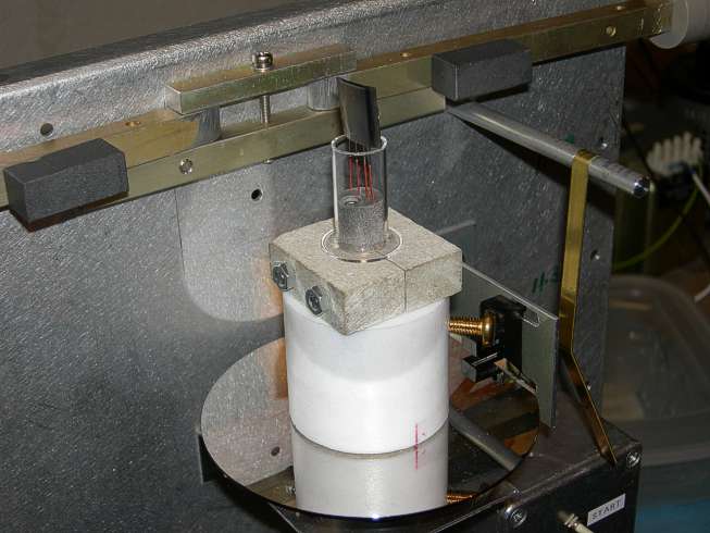
A 60mm length of 14mm OD tube is flared to the diameter of the envelope on the lathe. It is then cut to 28mm in length and mounted on the jig, which also holds the Dumet wires. A motor and worm drive rotates the jig at low speed. A hard-disk with a slot cut in it and an optical sensor from an old printer are used with some logic gates to make the jig stop in the correct position when the Stop button is pressed. The graphite blocks on the arms are then used to pinch the tube closed. This has to be repeated a number of times until the Dumet wires are fully sealed to the glass. This is apparent by the bright red colour. The stem then requires immediate annealing. To make this possible, the jig is made from Syndanio board (containing asbestos) and stainless steel nuts and bolts. The jig stands on studs and can be lifted off (wearing gloves) and placed in the annealing oven which has been pre-heated to 300°C. The oven is then heated to 530°C as quickly as possible. The temperature is maintained at 530°C for 20 minutes and then ramped back down to ambient temperature slowly.
For the filament, a 25mm length of 0.075mm diameter pure tungsten wire was used. Data by Jones and Langmuir shows that this filament should have the following characteristics:
| Current (A) | Temperature (K) | Emission (A) | Life(h) |
|---|---|---|---|
| 0.924 | 2400 | 4.9 | 2742 |
| 0.991 | 2500 | 12.6 | 1560 |
| 1.060 | 2600 | 30.4 | 359 |
| 1.131 | 2700 | 69.1 | 100 |
| 1.201 | 2800 | 150.0 | 28 |
| 1.274 | 2900 | 309.8 | 9 |
The life is defined as the time taken for 10% of the filament to evaporate.
The anode (or plate) was made from a 25mm length of 14mm OD nickel tube. The chosen grid design is that of a wire helix as this structure is well documented and easy to make. The dimensions of the anode and grid determine the amplification factor μ of the triode. The amplification factor is defined as the ratio of the change in anode voltage to the change in grid voltage required to cause the same change in anode current. The following calculations give a prediction of μ for the chosen dimensions. The length of wire and number of turns required for the grid spiral are also calculated to assist with winding it.

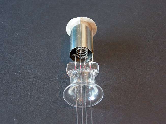
All joints between metal parts (except for the filament) were made by spot-welding using a homemade spot welder. Connection to the filament was made by flat nickel sheet, folded over and crimped. A mica disc was fitted to keep the electrodes concentric with each other and with the glass envelope.
The electrode assembly was immersed in trichloroethylene in an ultrasonic bath for 10 minutes. It was then rinsed in distilled water and then isopropyl alcohol. It was then dried with warm air. The envelope was rinsed out with isopropyl alcohol and dried with warm air.
The stem was joined to the envelope using the motorized jig. Once cool, the triode was attached to the pumping rig and evacuated. The anneal / bake cycle was then started.
The temperature ramp rates were set very low due to the use of soda-lime glass instead
of the lead glass used for commercial tubes and also because being evacuated, the stem
pinch behaves thermally as if it is about 6mm thick.
168°C/h to 400°C (136 min).
60°C/h to 530°C (130 min).
Dwell at 530°C for 30 min.
60°C/h to 400°C.
168°C/h to ambient.
At this stage I was not sure that the viscosity of the glass would be high enough at 530°C to withstand the air pressure. I was not sure what I would find when I opened the oven.
The oven was opened all was well. At this stage, it was getting late, so I left it pumping over-night.
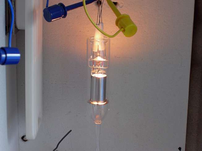
The next day, the filament was connected to a power supply and operated at 1.13A for nominally 2700K. The rig pressure was 4x10⁻⁵mbar. The pressure ideally should be somewhat lower than this.
A homemade induction heater was then used to heat the anode to red-heat. This was only maintained for around 10 seconds until a capacitor in the induction heater failed. I decided to close off the exhaust anyway and see if the triode had any life in it.
The characteristic curves of the triode were plotted for various grid voltages and are shown below. This is for a filament current of 1.28A. The characteristics were unstable and the emission current was low. The anode slope resistance is low. There are abrupt kinks in the curves. All these characteristics are indicative of the presence of gas in the triode. The curve for a grid voltage of 0V looks quite normal because the ionizing potential of the gas has not been reached. At higher potentials, positive gas ions partially neutralize the space charge, causing a rapid rise in current.
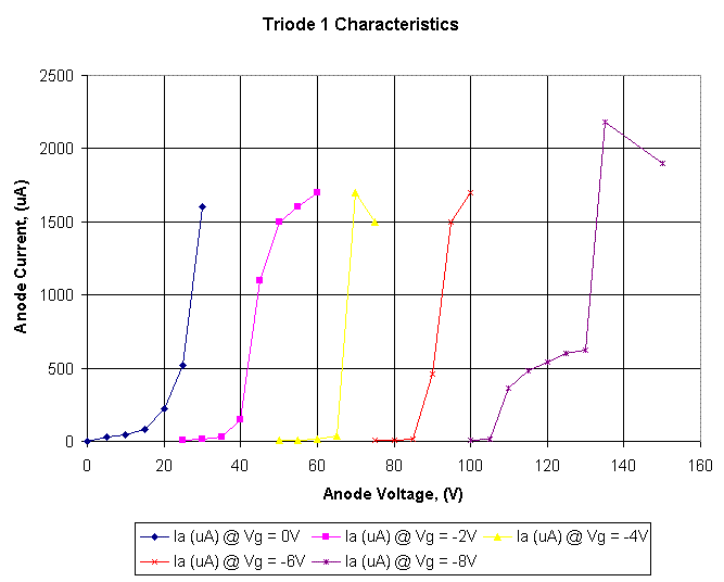
Claude Paillard predicted that if there was gas present (poor vacuum) then the emission current would gradually improve as the filament evaporated and acted as a getter. This was indeed the case. When first operated, the emission current was 1.1mA with 1.28A filament current. This gradually increased to 2.6mA.
Poor vacuum was confirmed by measuring the ratio of ion current to electron current.
With +150V on the anode (Va) and -2.5V on the grid (Vg), the filament current (If) was
increased until measurable anode current flowed. The grid current (Ig) and anode current
(Ia) were then measured. For a good triode, the ratio of Ia / Ig should be greater than
1000. The following results were obtained:
Va = +150V
Vg = -2.5V
If = 1.11A
Ia = 160μA
Ig = 4.6μA (Conventional current flow out of the grid)
Ratio = 34.8
This is clearly a very soft tube.
Considering that this was the first attempt, I am quite pleased with the results. In some ways I am pleased that the triode was soft (poor vacuum). The characteristics are rather interesting and I learned far more than I would have if it had worked first time.
There are a number of things that can be done better on the next attempt:
It is important to make the conductance of the exhaust tube as high as practically possible. Calculations show that the conductance of the exhaust tube was only 0.022 liters/sec when the necking is taken into account. The pressure gauge is measuring rig pressure. Due to the resistance offered by the exhaust tube, the pressure inside the triode will be higher than indicated. This makes it particularly important to measure the triodes ion current, effectively using it as a gauge head. Avoiding the necking and reducing its length to 92mm will increase the conductance to 0.059 l/s.
Hopefully the next one will be better.
| Previous Page | Glass Blowing Menu | Main Menu |
|---|