
X-Rays
DANGER: X-rays are a form of ionizing radiation and can cause severe tissue damage
and cancer. The high voltage required is also a serious hazard. I do not recommend
that you attempt to replicate the following experiment. Never attempt to X-Ray body
parts unless you are a qualified radiologist.
IMPORTANT NOTE: During the following experiments, the vacuum chamber was surrounded
by lead shielding. I used X-rays with a maximum energy of 50keV which made shielding
relatively easy. X-ray leakage was reduced to a safe level.
Background Information
X-rays were discovered by Wilhelm Conrad Rontgen in 1895. The potential for medical
use was immediately recognised.
X-rays are electromagnetic waves in the 1016 to 1020Hz
region but it is more convenient to refer to their energy in electron volts (eV)
rather than frequency. The relationship between energy and frequency is E = hf
where E is the energy in joules (J), h is Planck's constant (6.626x10⁻³⁴Js)
and f is the frequency in Hz. Joules can be converted to electron volts by dividing
by 1.6x10⁻¹⁹.
X-rays are emitted when electrons are accelerated in a vacuum and made to collide
with a target. Very early tubes contained gas at low pressure and had a cold cathode.
Modern tubes have a thermionic cathode and are fully evacuated. This allows the
acceleration voltage and the electron beam current to be controlled independently.
The frequency spectrum of the X-rays depends upon the acceleration voltage which is
usually well in excess of 40kV. Increasing the current (by increasing the filament
temperature) increases the intensity of the X-rays but leaves the frequency spectrum
unchanged.
When electrons hit a target they produce X-rays by two mechanisms. When an electron
passes very close to a target atom's nucleus, it gets deflected. This is called
bremsstrahlung which is a german word meaning 'breaking radiation'. It produces a
continuum of X-ray energies up to the energy of the electrons bombarding the target.
Hence if the acceleration voltage is 50kV, the maximum X-ray energy will be 50keV.
The maximum frequency is then (50x103 x 1.6x10-19) /
(6.626 x 10⁻³⁴) = 1.2x10¹⁹Hz. The wavelength λ = c/f
where c is the speed of light (3x10⁸ms-1), so the shortest
wavelength of 50keV X-rays is 3x10⁸ / 1.2x1019 = 0.025nm.
When an electron collides with one of the inner electrons of a target atom, ejecting
it, another electron replaces it, losing energy in the process. This energy is
released as an X-ray photon with a frequency characteristic of the target material.
This produces a series of peaks in the spectrum which are referred to as the
characteristic radiation. Tungsten is normally used for the target because it
has a very high melting point (3382C) and a high Z number (74).
Shielding
Generally speaking, the denser the material, the thicker the material and the
lower the X-ray energy, the greater the attenuation is.
Calculating attenuation by a material is quite straight forward. The calculation
considers a single energy whereas a practical X-ray source emits a continuum up
to the maximum as explained above. For calculating the necessary shielding, this
is not a problem. The highest energy is most penetrating so calculating for the
highest energy gives the worst case. Attenuation Iin/Iout = exp (-μx) where
μ is the linear attenuation coefficient and x is the thickness of the material.
The value of μ depends upon the material and the energy.
Linear Attenuation coefficient of Some Materials.
|
| 40keV
| 50keV
| 60keV
| 80keV
|
| Material
| μ (mm-1)
| μ (mm-1)
| μ (mm-1)
| μ (mm-1)
|
| Gold (Au)
| 25.1
| 14.0
| 8.75
| 4.22
|
| Lead (Pb)
| 16.3
| 9.11
| 5.69
| 2.74
|
| Copper (Cu)
| 4.36
| 2.34
| 1.43
| 0.684
|
| Nickel (Ni)
| 4.09
| 2.20
| 1.35
| 0.650
|
| Aluminium (Al)
| 0.154
| 0.0995
| 0.0751
| 0.0545
|
| Borosilicate glass
| 0.109
| 0.0759
| 0.0607
| 0.0474
|
| PTFE (Teflon)
| 0.0577
| 0.0465
| 0.0410
| 0.0356
|
So, if 1.8mm thick lead sheet is used, the attenuation of 50keV X-rays will be
exp(-9.11 x 1.8) = 7.6 x 10⁻⁸. For practical considerations, 50keV X-rays
are therefore completely stopped by 3mm of lead.
 I purchased a large roll of lead flashing from Jewson. It was the largest they had
in stock (0.6m by 6m by 1.8mm thick). It weighed 72kg and cost �81. I got some odd
looks from the Jewson staff. They probably thought I was building a cathedral.
I purchased a large roll of lead flashing from Jewson. It was the largest they had
in stock (0.6m by 6m by 1.8mm thick). It weighed 72kg and cost �81. I got some odd
looks from the Jewson staff. They probably thought I was building a cathedral.
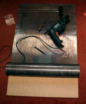
I made a shield for the front of the vacuum rig by screwing lead sheet to a 0.6m
by 1m chipboard sheet. I also made a wooden box to fit over the vacuum bell jar
and covered it with lead sheet. I fitted two handles to assist with lifting it.
Lead sheet is very soft and can be cut with a large pair of scissors or tin snips.
Lead is poisonous so it is important to wash ones hands after handling it.
X-rays can be detected with an ordinary Geiger counter like the one described in the
electronics section. Unfortunately Geiger counters are less sensitive to low energy
X-rays than they are to gamma. The implication of this is that dose meters designed
for gamma will tend to underestimate X-ray dose.
Another important thing to know is that pointing the X-ray beam away from you does
not protect you from being irradiated. Compton scattering by the target will send
X-rays back at you at a different energy. Hence it is important that the shielding
fully encloses the source and target.
EHT Supply
The EHT supply can be seen under test in the photo below. The bowl is there
to catch leakage of transformer oil.
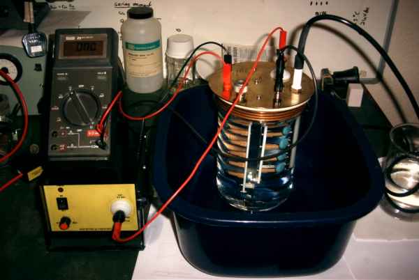
I used a high voltage ac power supply (the unit with the yellow front panel)
followed by seven diode-capacitor multiplier stages which are in the bowl on the
right of the picture. The ac power supply is a home made unit which uses a b/w
television flyback transformer with a re-wound primary. Instructions on how to
build this power supply can be found in the book 'Build Your Own Infrared and
Laser Space-Age Projects' by Robert E. Iannini.
The multiplier is followed by a divider which gives 1V per 10kV to allow the
EHT to be monitored using an ordinary volt meter. The multiplier and divider
were immersed in Electrolube TRO transformer oil. This is available from RS
Components (stock number 423-7363). The EHT supply can produce 64kV open
circuit and 50kV at 0.5mA.
The 'Tube'
 I have seen various articles which horribly abuse old vacuum tubes to produce X-rays.
I thought I would try something a bit more adventurous, so I decided to use the
vacuum rig. Normally the electrical connections into the vacuum chamber go through
the aluminium base plate. This would flash-over at 50kV. Luckily I had a spare bell
jar with a hole in the top.
I have seen various articles which horribly abuse old vacuum tubes to produce X-rays.
I thought I would try something a bit more adventurous, so I decided to use the
vacuum rig. Normally the electrical connections into the vacuum chamber go through
the aluminium base plate. This would flash-over at 50kV. Luckily I had a spare bell
jar with a hole in the top.
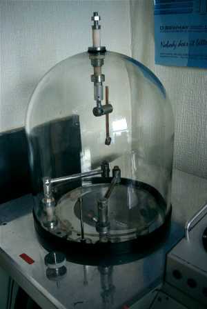
I fitted an electrical feed-through to the hole in the top of the bell jar using
rubber gaskets to seal it and protect the glass. The bell jar is about 7mm thick
and so will absorb about 50% of the X-rays. There was not much I could do about that.
The target is a square piece of tungsten brazed to a copper rod. The rod is clamped to
the feed-through at the top of the bell jar. The filament is clamped between the ends
of the two horizontal aluminium rods. It is 0.2mm pure tungsten wire bent into a
hairpin shape.
Operation
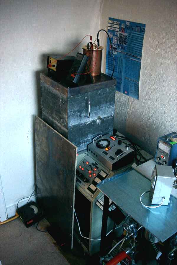
I put the EHT supply on top of the bell jar shield to keep the high voltage cable
as short as possible. The AVO on the floor is measuring the electron beam current.
The filament current is provided by the vacuum rig supplies and adjustable by the
large black knob on the top console. This sets the beam current. I used 0.2mm diameter
pure tungsten wire which required 3.7A for an emission current of 0.5mA. The meter in
the blue case on the right is measuring the pressure in the bell jar
(1x10⁻⁴mBar).
I used standard Ilford Multigrade IV black and white photographic paper for the film.
No doubt proper X-Ray film would work better and probably not require such long
exposure times. I wrapped each piece of film in aluminium cooking foil. This
was primarily to enable it to be used in daylight but also because I suspected that
electron emission from the foil would help to expose the film.
Results
I developed the film using Ilford Multigrade Paper Developer. The fixer was Ilford
Rapid Fixer. Both were mixed 1:9 with water. I did not bother with a stop bath.
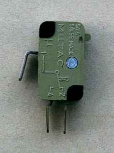
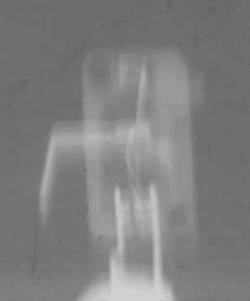
Above is my first attempt. It is a microswitch imaged at 50kV 0.5mA. Exposure time
was 8 minutes. Note that it is a negative, so dense parts of the object appear white.
The white blob at the bottom is a lump of Blu-Tack.
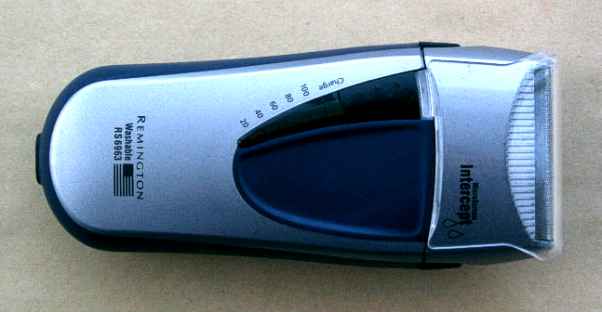
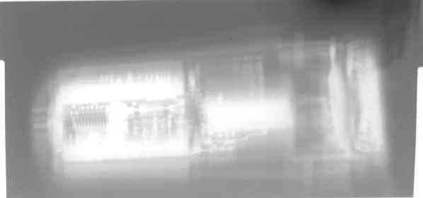
Above is a Remington electric razor imaged at 50kV 0.5mA. Exposure time was 20
minutes. The motor can be seen and also the batteries on the left. On the far left
the pins of the power connector can be seen.
I was quite pleased with the results, especially as the man in the camera shop where
I bought the film and chemicals said that it would not work at all. I plan to try to
collimate the beam as that should make the images sharper.
I suspected that the photoelectric effect was at least partly responsible for film
exposure. I decided to investigate the significance of this effect.
The Photoelectric Effect
The photoelectric effect is when electromagnetic radiation, incident on a metal surface
causes the emission of electrons. This only occurs if the photon energy is above a
threshold called the work function of the material.
Pure elements have work functions in the range 2.14eV for caesium to 5.9eV for selenium.
This gives threshold wavelengths from 580nm to 210nm. This range extends from yellow light
to deep ultraviolet. So, in theory, all metals should exhibit the photoelectric effect
when irradiated with X-Rays. With X-Rays, the amount of emission becomes dominated by
the photoelectric cross section of the metal.
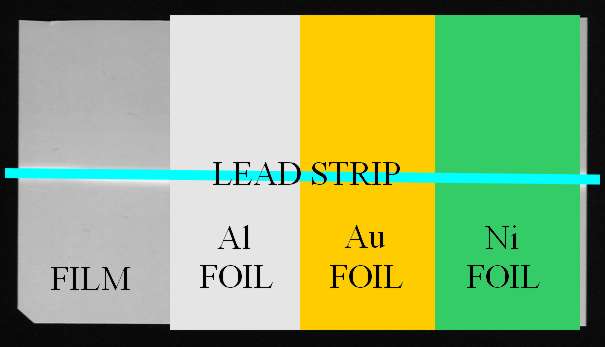
I wrapped a piece of film with a strip of 0.01mm thick aluminium (Al) foil. I also
wanted to try denser materials (which have greater photoelectric cross sections) so I
also wrapped the film with gold (Au) coated aluminium foil and 0.025mm thick nickel (Ni)
foil. The gold coated foil was prepared as described on the Evaporating Metal page.
A section of the film was left without foil for comparison purposes. The film / foil
was then placed in a light tight plastic box and a strip of lead taped to the outside
of the box to act as the object. The arrangement is shown in the following diagram.
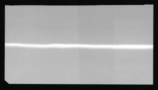
Exposure was at 50kV, 0.45mA for 12 minutes. The film was developed for 5 minutes
and the result is shown above.
As can be seen by comparing the film with the diagram above it, the effect of the
aluminium and nickel is negligible. The gold film, despite being probably only a
micrometer thick, has contributed significantly to the film exposure. This additional
darkening of the film is caused by bombardment by electrons emitted from the gold.
If the gold film was much thicker, its absorption would start to offset the enhancement
which is why I used a thin coating rather than a solid gold foil.
The images are not very sharp. I suspect this is mainly due to the relatively large
electron target and also scattering caused by the thick glass of the bell jar.
Some much better results using a commercial X-Ray tube can be viewed in the
X-Ray Gallery.