
| Experiments Menu | Teralab Main Menu |
|---|
This project was really just a bit of fun and is not as 'scientific' as most other pages on this site. It does have some interesting features though, particularly the 'spark gap switch'.
The High Energy Pulser is based upon plans published by Information Unlimited. It also uses some of their parts, including the neon sign transformer and trigger transformer. The main storage capacitors were acquired on eBay and most of the other parts were either already to hand or purchased from Farnell.
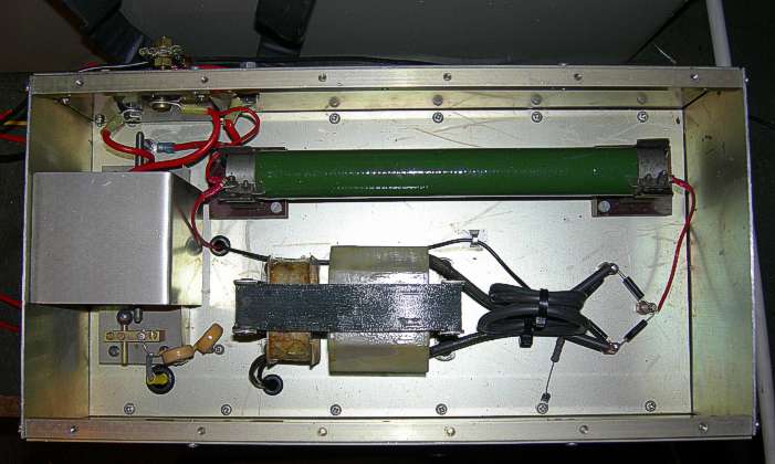
The top deck of the main unit is pictured above. In the middle is the neon sign transformer. At the top is a 10k wire wound resistor. It is not needed to limit the charging current because the neon sign transformer is inherently current limited. I think its purpose is to prevent the capacitor bank from discharging back through the bridge rectifier (bottom right) if the polarity reverses during a discharge. This can occur when discharging into an inductive load. Anyway, it was in the Information Unlimited plans, so I fitted it. The magic spark gap switch is under the guard cover on the left.
The spark gap switch was made from brass and peek stock material with tungsten rod for the main electrodes and a steel ball bearing brazed to a rod for the trigger electrode. The construction of the switch needs to be quite rigid because the magnetic forces acting upon it are quite considerable. I also found that I had to add a guard cover. When the switch fired, little balls of molten tungsten were getting ejected and were damaging other components. The guard cover contains the spray and also cuts down the noise slightly. Interestingly, the spray always goes in the same direction. Perhaps it is being repelled by the current in the adjacent wire. Any thoughts anybody?
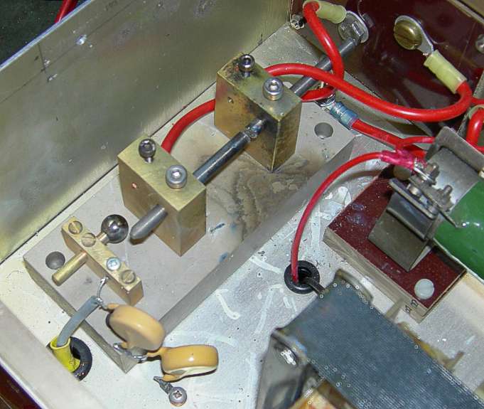
Above is the spark switch. It is one of those things that looks as though it shouldn't work, but it certainly does. The main gap consists of the two tungsten rods mounted in the two brass blocks. The rods are 5mm in diameter. This gap is in series with the capacitor bank and the load. The gap is adjusted so that breakdown does not occur when the capacitor bank is charged to full voltage (4200V). The round electrode on the left is the trigger.
To fire the pulser, a high voltage generator in the lower compartment charges the two yellow capacitors (above left). When the voltage reaches the breakdown potential of the air gaps, a spark jumps between the trigger electrode and the brass block and between the two main tungsten rod electrodes. This ionization of the main gap provides charge carriers for the current to start to flow from the main capacitor bank. This current keeps the arc sustained between the two tungsten rods until the capacitor bank is discharged. Vapourized metal probably assists this process. Typically the bank discharges to a few tens of volts. All electronics engineers are aware that an electrostatic discharge (ESD) can damage semiconductors, but it is a sobering thought that ESD could blow up a mains powered circuit. However this is just how the spark switch works.
With low impedance loads, it is necessary to include a ferrite ring in series with the load to allow sufficient voltage to be developed across the spark gap by the trigger circuit. When the capacitor bank current flows, the ferrite ring saturates and effectively disappears from the circuit.
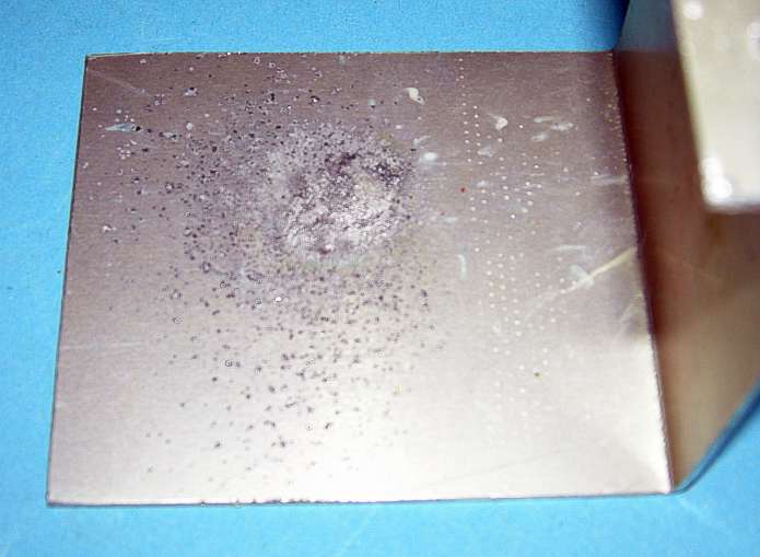
The spark guard cover is shown above with damage caused by molten tungsten concentrated in one area about 20mm in diameter. Very little material goes in any other direction.
I added a countdown timer to the basic design and that turned out to be a very good decision that probably saved me from injury. While experimenting with a plasma cannon, the breech block exploded breaking the room light and leaving dents in the ceiling. I was safely cowering in the next room. Luckily the camera survived and this event can be seen in the movie at the bottom of this page. The timer and high voltage trigger circuits are on a Vero PCB in the lower compartment of the main unit along with a 12V power supply.
I also made a discharge crook consisting of twelve 10k Welwyn W23 resistors in series. The resistors were threaded into a ceramic tube and a conductive hook fitted at one end. The other end was connected to earth. This crook is an essential item as if the trigger circuit fails to fire the spark switch, it is the only safe way of discharging the capacitor bank to allow investigation of the fault.
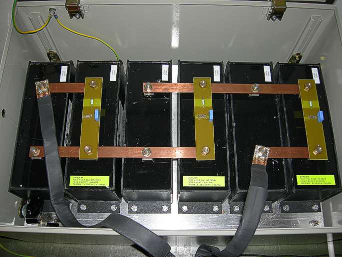
Above is the capacitor bank. The capacitors were obtained on eBay and were made by Electronic Components Europe. I mounted them in an earthed steel cabinet for electrical safety and because initially I did not know if they were suitable for this type of duty and might explode. Each capacitor is 300uF 1400V giving a maximum stored energy of 0.5 C V2 = 1760J.
The capacitors are in a series, parallel configuration and across each parallel pair there is a neon indicator that flashes if the capacitors have more than about 60V across them. This is another safety feature.

Can crushing is done with a coil of about 6 turns wrapped closely around the can. Both the rate of change of current and the peak current in the coil need to be as high as possible. The changing current in the coil produces a changing magnetic field that induces current in the can. The current flowing in the can also produces a magnetic field that opposes the field from the coil. This is the basis of Lenz's law. The can thus experiences a force that tends to crush it inwards. An equal and opposite force acts on the coil and if the coil is not strong enough, the coil diameter increases each time it is fired. My can crusher never performed as well as it should for the energy available. I suspect this is mainly due to energy wasted by the spark switch (the noise from which is ear splitting). Some of the results are pictured above. The middle can actually started to fracture, but I never managed to completely sever a can.
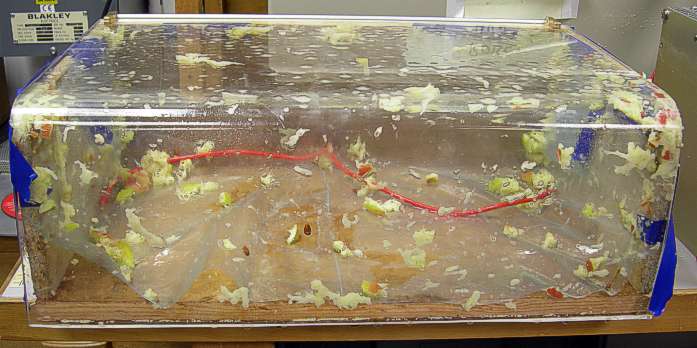
The High Energy Pulser can also be used as an Express Apple Sauce machine. A rod is pushed all the way through an apple and a pair of electrodes are then inserted until they almost meet in the middle. When the pulser is fired, the sudden gas pressure causes the apple to explode. A typical result is shown above.
The above movie is only a couple of minutes long and shows a few of the things that the pulser can do.
The pulser can also explode wire (which I have not tried, but believe is quite spectacular) be used with a pancake coil to launch metal disks (which I have tried but I lost the footage) and also for the defibrillation of elephants.
| Experiments Menu | Teralab Main Menu |
|---|