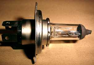
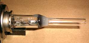
 This is a Philips 12V 60/55W halogen headlamp bulb with a failed main beam filament. There are
three connector pins on the base, allowing the two filaments to be switched independently.
The envelope is high temperature quartz glass.
This is a Philips 12V 60/55W halogen headlamp bulb with a failed main beam filament. There are
three connector pins on the base, allowing the two filaments to be switched independently.
The envelope is high temperature quartz glass.
| Experiments Menu | Teralab Main Menu |
|---|
I had to replace a headlamp bulb on my car recently. I threw the old one in the bin. A few minutes later, I had a brain-wave and got it back out again. Headlamp bulbs have two filaments, one for dipped beam and the other for main beam. With the dipped beam filament blown, the remaining structure is pretty close to a Fleming Valve.
The Fleming Valve was invented by John Fleming in 1904 and was the first practical thermionic device. It was basically a modified electric lamp which had a metal plate next to the filament. Electrons released by the filament were attracted towards the plate by an electric field. The Fleming Valve behaved as a diode.
I decided to try to make the headlamp bulb function as a diode valve and then to measure its characteristics.
This is a Philips 12V 60/55W halogen headlamp bulb with a failed main beam filament. There are
three connector pins on the base, allowing the two filaments to be switched independently.
The envelope is high temperature quartz glass.
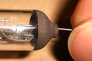
 The pump seal of the lamp is actually on the end like an early carbon filament lamp. It can
cut off easily and cleanly using a diamond saw.
The pump seal of the lamp is actually on the end like an early carbon filament lamp. It can
cut off easily and cleanly using a diamond saw.
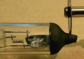
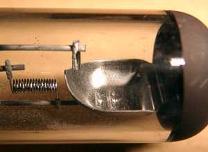
In this photograph, the filaments can be seen more clearly. The failed dipped beam filament
is on the right-hand side. When this filament has been removed, there will be an
open-circuit post next to the left-hand filament. The post connects to one of the pins on
the base and can be used as the anode of a thermionic diode. The left-hand filament becomes
a directly heated cathode.
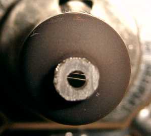 This is the end of the lamp after the pump seal has been cut off.
The lamp had to be cut open, because it originally contained halogen gas. This would
breakdown when sufficient anode voltage was applied.
The filament must not be heated with the bulb full of air, because it would quickly
burn-out.
 The failed filament was very brittle and could be broken up with a bent piece of wire,
inserted through the hole in the end of the lamp. The broken pieces of the filament could
then be shaken out.
The failed filament was very brittle and could be broken up with a bent piece of wire,
inserted through the hole in the end of the lamp. The broken pieces of the filament could
then be shaken out.
 Once the main beam filament has been removed, what remains is the structure of a Fleming
Valve. The horizontal post at the top of the picture will function as the anode. The
filament beneath it, will be the cathode.
Once the main beam filament has been removed, what remains is the structure of a Fleming
Valve. The horizontal post at the top of the picture will function as the anode. The
filament beneath it, will be the cathode.
 To enable the bulb to be evacuated, a short length of 8mm diameter glass tube was attached
using Araldite Rapid.
To enable the bulb to be evacuated, a short length of 8mm diameter glass tube was attached
using Araldite Rapid.
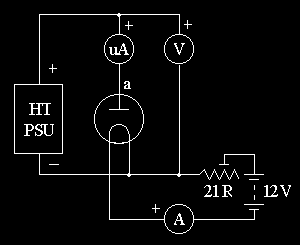 This is the circuit I used to measure the characteristics. The variable resistor in the
filament circuit was a 21Ω 6.5A rheostat. It was used to adjust the filament current.
A 10Ω rheostat would probably have provided finer and more stable control of the
filament current.
This is the circuit I used to measure the characteristics. The variable resistor in the
filament circuit was a 21Ω 6.5A rheostat. It was used to adjust the filament current.
A 10Ω rheostat would probably have provided finer and more stable control of the
filament current.
The 12V supply for the filament was a 4AH Yuasa sealed lead/acid battery. Later, when it
ran flat, I switched to a 6AH one.
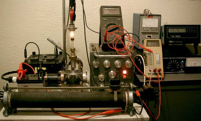
The test equipment is shown in the photograph below. The filament current was supplied by the 12V lead/acid battery on the left. The filament current was adjusted using the rheostat at the front of the picture. The AVO meter at the rear-left was used to measure the filament current. The large unit with the red light on it is a variable EHT supply. The two digital multimeters were measuring the anode voltage and current. The meters on the far right were measuring the pump pressures. The pressure in the bulb was reduced to 3x10⁻⁵mBar. In the picture, the headlamp bulb can be seen lit at about 2A.
The results were tabulated and then graphs were plotted using Excel. The results are shown below. The y axes of both graphs are in μA.
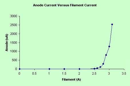 This graph shows how the cathode emission current varies with filament current. The anode
voltage was fixed at +500V dc.
This graph shows how the cathode emission current varies with filament current. The anode
voltage was fixed at +500V dc.
Very little current flows in the anode until the filament current reaches 2.5A. At this
current, the filament reaches a critical temperature where electrons acquire enough energy
to leave the material and are then free to move towards the anode.
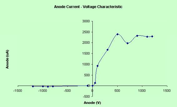
For the graph below, the filament current was fixed at 3.0A. The anode voltage was then varied, both positive and negative and the anode current plotted. A much larger current flows when the anode is positive than when it is negative. This is diode action and can be used for rectification, or to 'detect' AM radio signals. When the anode voltage is increased above about 500V, the current no longer rises because all electrons which are released from the cathode are reaching the anode. The dip in the curve at 700V was probably caused by the filament current drifting down.
| Experiments Menu | Teralab Main Menu |
|---|