Virtual Science Museum
Scientific Instruments - Page 2 of 2
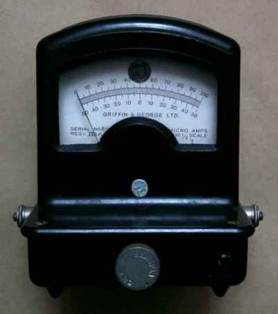 The next item is a Griffin & George Ltd. Microid Adaptable Galvanometer.
It has a full scale deflection of 14 micoamps. It has adjustable feet and
a spirit level in the dial.
There is a glass window at the rear of the instrument, behind which is a
mirror attached to the moving coil. This enables the instrument to project
a moving light spot.
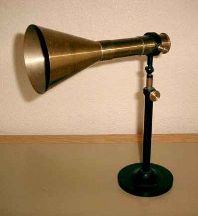 This is a thermopile radiometer designed for classroom demonstrations
of the detection of heat at a distance.
It was made by Philip Harris Ltd. Birmingham. The stand is fully
adjustable and can be raised and lowered. The 3.25 inch diameter
horn is removable and can be fitted with or without an extension tube.
Except for the insulators, it is made entirely from brass.
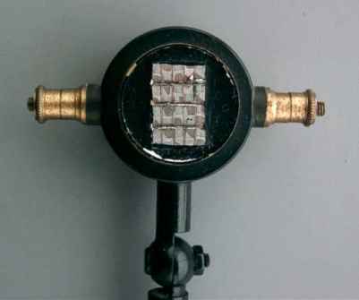 Inside the removable brass end cap there is an array of bismuth antimony
thermocouples which are quite sensitive. Putting my thumb on one side
gives a reading of just over 2mV.
The next item is a Coil Resistance 200 Ohms Mk1. It was made by Gambrell
Bros. & Co Ltd. London and is dated 1940. It is a special form of
Wheatstone bridge designed for testing blasting circuits. It would have
been used by the Royal Engineers in conjunction with a galvanometer and cell.
It can be configured in several different ways to test different aspects of
demolition circuits. The two clamps, bottom right, are for holding a fuse
wire when testing dynamo exploders.
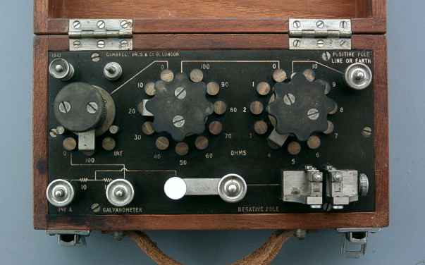
A Wheatstone bridge can be used to compare an unknown resistance
with the accurate resistors in the box. The bridge would be adjusted
to null the current through the galvanometer. When the bridge is balanced,
no current flows through the galvanometer. This makes it a very sensitive
way of matching resistances. The comparing resistance can be set in 1 ohm
steps from zero up to 200 ohms.
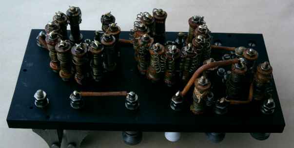
Inside the Wheatstone bridge, the resistors are wire wound on bobbins
which are bolted to the brass selector switch terminals.
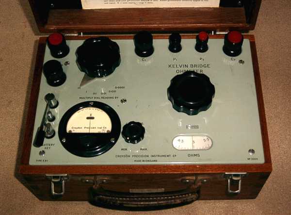
The next item is a Kelvin resistance bridge. It was made by Croydon
Precision Instrument Co. England and is dated 1957. The controls would
be adjusted to set the meter in the bottom left corner to center scale.
The resistance is then read off from the dial on the right. The meter
includes a mirror to avoid parallax error. The meter is read so that
the reflection of the pointer is hidden behind the pointer. The controls
have that well crafted feel only found in vintage equipment.
The measuring range is 50μΩ to 105Ω with an accuracy of
0.5%. A 2V accumulator is required for power.
 The next item is a Griffin & George Ltd. Microid Adaptable Galvanometer.
It has a full scale deflection of 14 micoamps. It has adjustable feet and
a spirit level in the dial.
 This is a thermopile radiometer designed for classroom demonstrations
of the detection of heat at a distance.
 Inside the removable brass end cap there is an array of bismuth antimony
thermocouples which are quite sensitive. Putting my thumb on one side
gives a reading of just over 2mV.

