
| Electronics Menu | Teralab Main Menu |
|---|
This page describes the development of electronics to display a monochrome video image on an electrostatic oscilloscope tube. This work is complementary to the Electron Optics page in the Experiments section. The ultimate goal is to display a moving video picture on a completely home made cathode ray gun inside the bell jar of a vacuum rig. For this reason I chose to use a 1950's RCA 3RP1-A oscilloscope tube. It is very similar in specification to my homemade electron gun and so is well suited to the development of the electronics. It should ultimately be possible to disconnect the RCA tube and connect the homemade one.
The circuit is designed for use with a PAL composite video signal, but it should be possible to adapt it for use with NTSC or SECAM by changing a few component values. In particular, the ramp rates of the sweep integrators may need to be adjusted slightly.
I chose to use a Sanyo LA7801 synchronization and deflection IC. This was the most suitable part in my bits box for which I could obtain a data sheet. This part is obsolete but could probably be obtained from an old television. Other timebase ICs could be used with appropriate alteration of the circuit. The circuit is closely based upon that provided in the data sheet. Click on the schematic below to see it in higher resolution.
The line pulse output at pin 4 of the LA7801 consists of a 2V, 25us long positive rectangular pulse. The rising edge coincides with the start of the line. The field pulse output at pin 6 consists of a 3V, 1.5ms long positive rectangular pulse which coincides with the field blanking period. The integrators (below) ramp freely until reset by the FETs (TR1 and TR2). This gives the required 'saw tooth' sweep waveforms. One PAL line lasts 64us, so the horizontal integrator ramps to 9.6V before resetting. A field (there are two fields to a frame) lasts 20ms, so the vertical integrator ramps to 9.4V before resetting. Potentiometers R23 and R28 set the horizontal and vertical picture size.
The timebase circuits were constructed on breadboard. This is just about acceptable with the frequencies involved.
The oscillograph below shows the operation of the horizontal scan integrator. The probes used were x10. From top to bottom, the traces are IC1 pin 4 (2V / division), TR1 gate (5V / division), IC3 pin 6 (10V / division) and the video signal at IC301 pin 6 (1V / division). The video amplifier is described later. The square pulses in the video waveform are the line synchronization pulses and are extracted by the sync separator in the timebase (IC1) to lock the horizontal sweep.
.jpg)
The RCA tube has a vertical deflection factor of 52 to 70V per inch per kV of accelerating voltage, so a high voltage drive is required. An ECC81 double triode valve was chosen for the high voltage output. Operational amplifiers in the feedback improve the linearity and set the voltage gain. Click on the schematic below to see it in higher resolution.
R105 and R104 provides the feedback from valve V101a. The anode voltage is divided by 19 and fed back to the op-amp. R101, R102 and R103 set the inputs of op-amp IC101A to around 5.3V. Thus the anode voltage is set to about 100V (half the HT voltage). Potentiometer R103 adjusts the horizontal picture position. D101 protects the op-amp. C102 and C104 are for high frequency stability. IC101B and associated resistors invert the input signal and apply it to a second valve output stage comprising V101b and IC101D. The horizontal deflection plates are connected to the valve anodes and are driven in bridge mode. This provides a differential drive of almost 400V peak to peak from a 200V supply. IC101C is not used.
An ECC81 double triode is again used for the high voltage output. The bandwidth of the LM348 op-amp used in the vertical amplifier proved to be inadequate for the horizontal amplifier and so it was replaced by an LF347. The LF347 has adequate bandwidth and I happened to have some in my bits box. Click on the schematic below to see it in higher resolution.
The values of C102 and C105 have been reduced and C104 and C105 have been removed to increase the bandwidth. C101 has been greatly reduced in value as the frequencies being amplified are much higher. Everything else is the same as for the horizontal amplifier.
R112 in parallel with R3 in the timebase gives approximately the right input impedance of 75Ω. R301 adjusts the contrast. IC301, R302 and R303 invert the video signal so that it is the right way up with positive sync pulses and peak white most negative. An EF85 pentode valve is used for the output for improved linearity to that of a triode. IC302 and associated resistors set the gain and DC biasing. R304 and C102 are for high frequency stability. The output is taken from the valve anode. Voltage gain from input to output is about 100.
D401 in the schematic below is the DC restoration diode for the video signal. It clamps the sync pulse tips to -900V. The anode of V101 connects to C401.
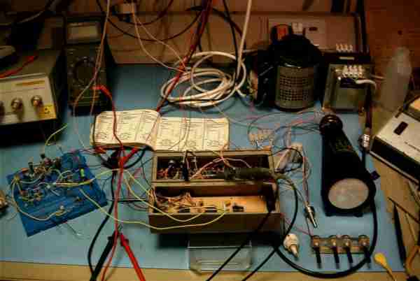
This is the bench lash-up. The power supplies are out of view on the shelves above the bench. The blue breadboard on the left holds the time bases and sweep integrators. The metal box in the middle holds the video and deflection amplifiers. The three valves are on the underside. The black cone on the right is the oscilloscope tube.
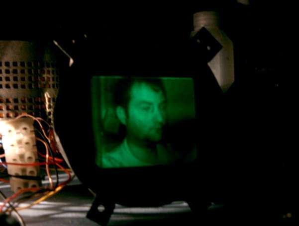
This is me imaged using a black and white CCD camera (Ł20 from B&Q). The black line between my nose and right eye is caused by a non-fluorescent patch on the screen. The bandwidth of the video amplifier is not really adequate and so some more work may need to be done in that area.
| Electronics Menu | Teralab Main Menu |
|---|