
| Electronics Menu | Teralab Main Menu |
|---|
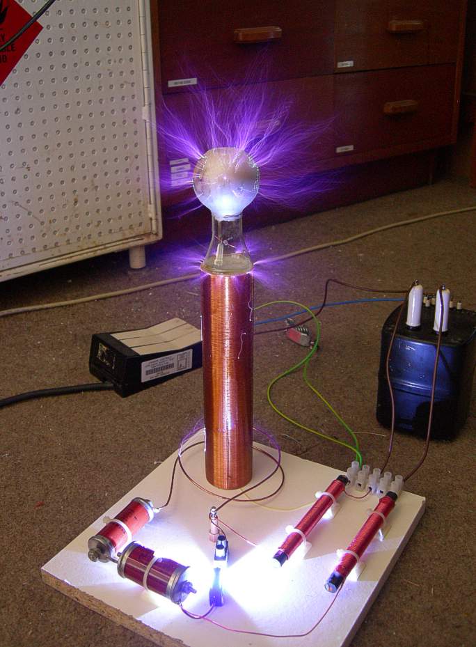
This is my first Tesla coil. It was inspired by an article in the March 1995 issue of Electronics World & Wireless World. Construction was much more straightforward than I expected. I am now tempted to build a bigger one. This is not intended to be instructions for building a Tesla coil, just documenting what I built.
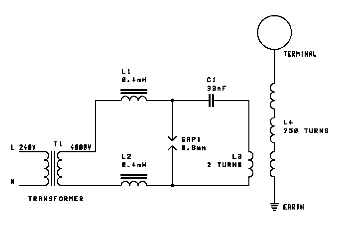
The Tesla coil consists of a primary resonant circuit (C1 and L3) and a secondary resonant circuit (L4 with self capacitance and terminal capacitance). The primary and secondary resonant frequencies must match. The mains transformer (T1) charges the primary capacitor (C1) until the spark gap (GAP1) fires. When this happens, the stored energy is applied to the primary coil (L3). There is loose coupling between L3 and L4, causing a very high voltage to develop across the secondary. The series chokes (L1 and L2) are to prevent RF energy passing back into the mains transformer (T1).
It is difficult to predict with reasonable accuracy what the resonant frequency of the secondary will be as it depends upon its self capacitance. I found it easiest to build the secondary first, measure its resonant frequency and then design the primary circuit to match.
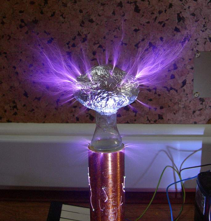
The secondary was wound by hand on a 200mm length of 40mm diameter drain pipe using 0.26mm diameter enameled copper wire. Double sided tape was used to prevent the windings from unravelling during construction. The top electrode was made from a glass flask, inverted and coated with conductive paint. The coil was varnished in an attempt to improve the insulation.
The primary coil should be about twice the diameter of the secondary and about 5 to 10% of its height. The inductance of this type of coil in micro-henries is (r2n2) / (9r+10h) where n is the number of turns and r and h are the radius and height of the coil in inches. Two turns of 1.6mm diameter enameled copper wire were used. The tank capacitors are a low inductance oil filled type manufactured by Plastic Capacitors Inc. A 50nF in series with a 100nF gave the correct resonant frequency.
The spark gap was made from two short pieces of tungsten rod, which were cut using a Dremel and a cut-off wheel. The chokes are wound on ferrite rods from old radios.
The primary and secondary resonant frequencies should match reasonably accurately. If the primary frequency is higher than the secondary, the options are:
If the primary frequency is lower than the secondary, the reverse applies.
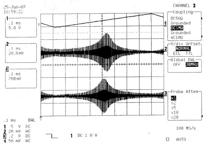
Above is the result of a resonance sweep test. The primary and secondary were kept separate, but tested simultaneously to see how their resonances compared. A sinewave sweep generator was connected to the bottom of the secondary coil and across the primary capacitor with the spark gap shorted. Trace 1 is proportional to the applied frequency. Trace 2 is the waveform across the primary capacitor. Trace 3 is from an oscilloscope probe placed 300mm away from the secondary coil. The sweep start frequency was 500kHz and the stop frequency 1500kHz. Resonance is just over 1MHz.
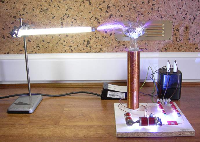
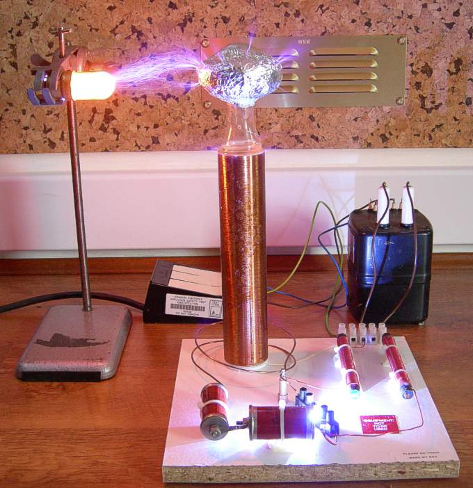
Various pictures of the Tesla coil operating are shown below. The maximum spark length achievable was around 100mm. Since the energy storage in the primary capacitor is only 267mJ, this is doing quite well. The coupling of the coils may be a little high as there is flash-over on the secondary when discharging into free space. Note the bright light coming from the spark gap.
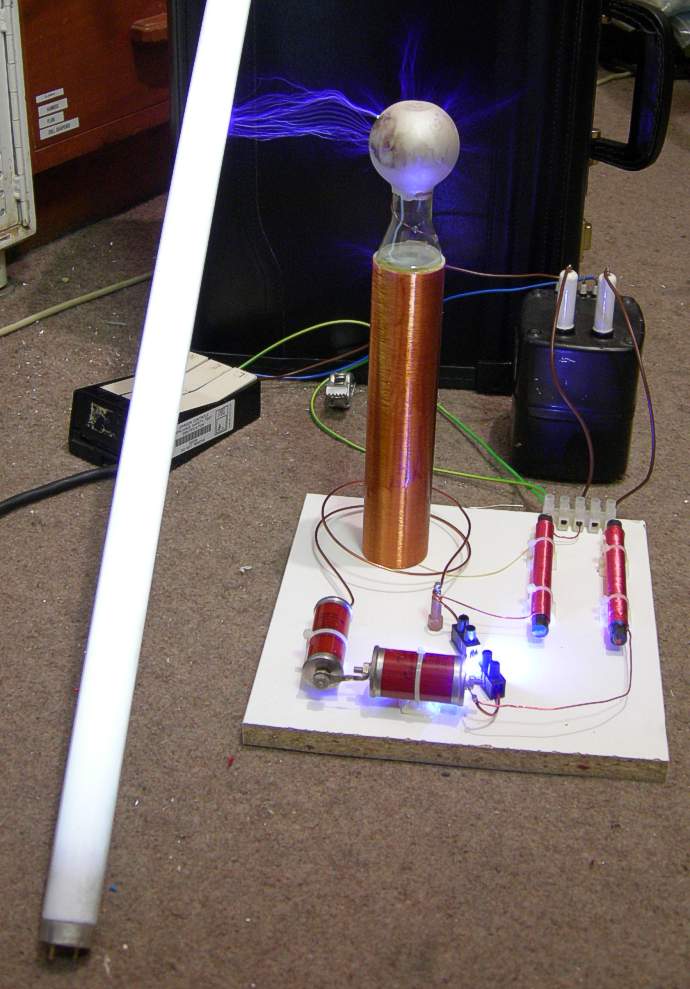
The size of the terminal was built-up to reduce the resonant frequency of the secondary slightly. This was done to try to make the frequencies match better and also because the conductive paint was burning off. The performance of the coil was not greatly improved by this modification.
I was a bit worried about the camera while taking this last picture.
| Electronics Menu | Teralab Main Menu |
|---|