
| Electronics Menu | Teralab Main Menu |
|---|
This project is a simple Geiger Counter which will detect beta particles and gamma rays. Indication is given by a speaker which emits one click for each count. With the addition of a counter circuit, counts per second can be indicated. I have found the sound only version of the circuit to be very useful for identifying radioactive items such as radium dial watches. The circuit will give many hours of operation from a single 9V PP3 battery.
The circuit is designed for use with a Mullard ZP1320 Geiger Muller tube. These tubes are now made by Centronic in the UK. The sensitivity of this tube is about 9 counts/s at 10μGy/h. It is sensitive to gamma and beta particles over 0.25MeV. It has a sensitive length of 28mm. Count rate versus dose rate is quite linear up to about 104counts/s.
This circuit is my design and may be distributed freely as long as I am given credit for it. Note though that this circuit is only intended to give an indication of the presence of ionizing radiation. It is not designed to be used as a dose meter. The aims of the circuit were simplicity and low power consumption.
Click on the schematic below to see it in higher resolution.
IC1C and IC1D form a 46kHz oscillator. The period for this type of oscillator is approximately 1.8CR. When pin 13 is high the oscillator free runs. Transistors TR1 and TR2 are turned on alternately to drive transformer T1. With the oscillator running, when TR1 is on, TR2 is off and when TR1 is off, TR2 is on. The high voltage output of T1 drives a multiplier network which consists of D1, D2, D3, C4, C5 and C6. C6 is the reservoir capacitor for the HT. IC2 compares the HT with a reference voltage. A divided down version of the high voltage supply appears at the inverting input. A 565mV reference is connected to the non-inverting input. As C6 charges, the voltage at the inverting input increases until pin 6 goes low. This switches off the oscillator via R9. With pin 6 low, both TR1 and TR2 are switched off. C6 then begins to discharge through R2. Eventually pin 6 goes high again and C6 charges back up. R8 provides about 20V of hysteresis on the HT. This method of operation leads to very low power consumption as TR1 and TR2 are off most of the time. R4 is adjusted to center the HT around 575V.
![]() For a parts list in Excel format, right click on the icon and choose 'Save Target As...'.
For a parts list in Excel format, right click on the icon and choose 'Save Target As...'.
The HT is connected to the Geiger-Muller tube via R12. IC3 with associated components provides pulse shaping with 22us integration and differentiation time constants. IC4A produces a 230us pulse for the speaker. The input thresholds of IC4A act as the pulse discriminator. The Q output of IC4A turns TR3 on to drive the speaker. The outputs of IC4A should not be used to drive a counter circuit because the maximum count rate will be limited. Instead, IC4B can be used connected to the output of IC3. The time period should be set to about 10us.
IC5 provides the 5V supply for the logic circuits.
I constructed the circuit on pad board (RS Components 206-8648) with hand wiring on the back. Obviously other construction methods such as etched PCB or strip board could be used. The only critical part of the layout is around C7, TR1, TR2 and T1. C7 should be located where the 9V supply enters the board. TR1, TR2 and T1 should be located close to C7 and connected with short tracks or wires to minimize the current loop area in that part of the circuit. Bad layout could cause false counts to be registered when the oscillator runs. All ICs should have local supply decoupling to 0V via 100nF capacitors (not shown on the schematic). Note that VCC must be connected to pin 16 of IC4 and 0V to pin 8. This is not shown on the schematic. Clearances around the high voltage components must be adequate for 600V. Also, C4, C5 and C6 must be rated to at least 600V, preferably 1000V. Note that C4 and C5 are 220pF but C6 is 220nF. R2 is a 1.5GΩ resistor. This very high value is used to minimize power consumption. Lower values could be used, but R3 and R4 would need to be altered to compensate. RS Components 228-1532 is suitable for the speaker.
The transformer is wound on a miniature ferrite core. The core type is RM6/F9 (RS Components 231-8713). The primary consists of 20 turns of 0.26mm enameled copper wire, center tapped. The secondary is 360 turns of 0.14mm enameled copper wire.
Other types of Geiger Muller tube could be used, but minor circuit alterations may be required. In particular, the HT voltage must be correct for the tube and R13 must be selected for 5V pulses at the cathode of the tube. The tube data sheet should be consulted and other circuit differences may be recommended by the manufacturer. Tubes with a mica window will detect alpha particles, but the window is very fragile and must not be touched.
The tube should not be connected via a long cable as that will add capacitance in parallel with it. This could lead to premature tube failure. Note that a shunt capacitance of as little as 20pF may destroy the tube.
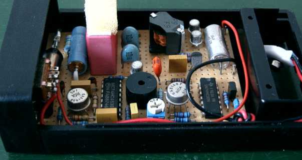
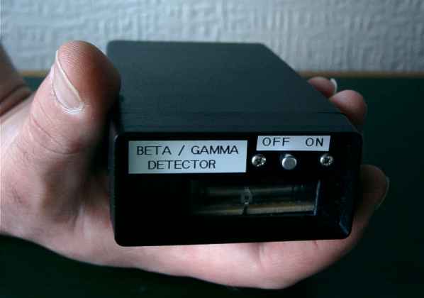
I housed the circuit in a pocket sized plastic box with integral 9V battery compartment. I cut a window in the front for the tube (for beta detection) and covered it with thin plastic film.
WARNING: It is important to treat the HT supply with care. C6 contains 36mJ of energy and remains charged 30 minutes after the supply is disconnected.
It is preferable to set the HT voltage with the tube disconnected. A high resistance meter probe is required for measuring the HT (Preferably 1GΩ). The voltage at the cathode of D3 is measured and R4 is adjusted to give an average voltage of 575V. It should ramp up and down by about 20V.
If the circuit is working properly there should be occasional clicks from the speaker caused by background radiation. The most easily available test source is an old radium dial watch. These can be obtained from antique shops for as little as a few pounds. Do not buy one with damaged glass and do not dismantle it. Radium is a powerful alpha emitter and is extremely dangerous if swallowed or inhaled, even in minute quantities. Radium emits alpha, beta and gamma. The alpha particles are absorbed by the glass of the watch, but beta and gamma penetrate and can be detected.
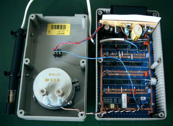
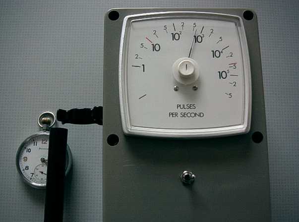
For a measurement of count rate, the output of IC3 can be connected to a counter/timer or a counter circuit can be added on. I have constructed a version of the Geiger Counter with a log counter built in. This drives an analogue meter with a logarithmic scale. The unit is much more bulky than the sound only version. The tube is housed in a wand which can be clipped to the side of the unit.
Here a WW2 pocket watch is being measured. This is a rather nice watch which I picked up in an antique shop for Ł40. I don't wear it because it measures 29μSv/h at 100mm with a calibrated meter.
| Electronics Menu | Teralab Main Menu |
|---|